What's in the box?
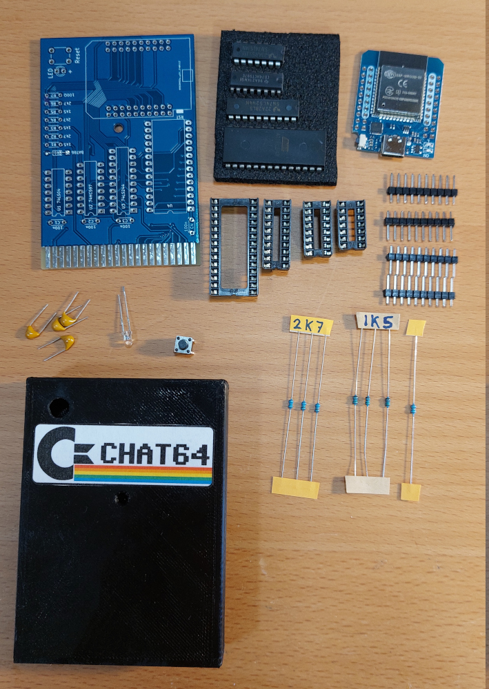 |
The kit contains:
- a custom pcb
- an 8kb EEPROM at28c64b
- an sn74ls244n ic (or equivalent)
- a cd74hct597e ic (or equivalent)
- an sn74ls14n or 74ls04 ic (or equivalent)
- ic sockets for all chips
- a D1 Mini ESP32 module
- pin headers for the ESP32 module
- 4 100n capacitors
- a red LED
- a tactile switch
- 3 2k7 ohm resistors (1/8 watt)
- 3 1k5 ohm resistors (1/8 watt)
- 1 100 ohm resistor (1/8 watt)
- a 3d printed cartridge enclosure
|
|
If you built it, they will come.
Before anything else
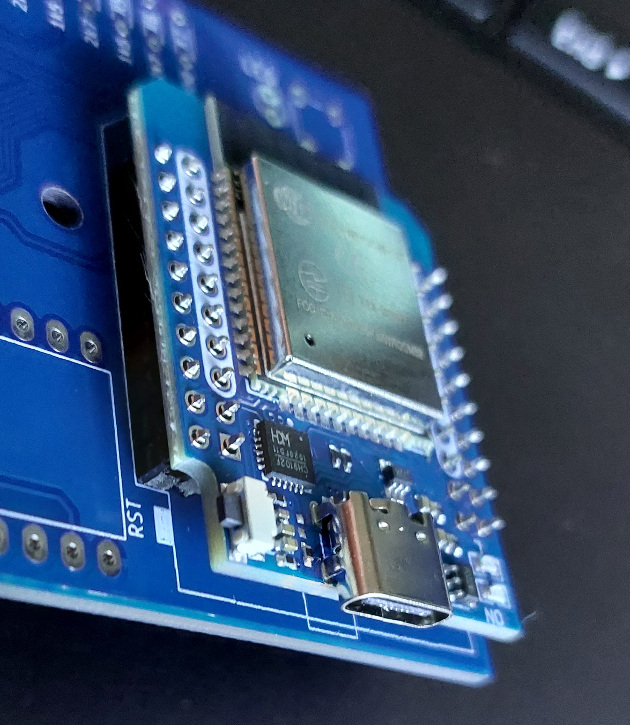
Make sure that all components are placed on the TOP side of the board. If you are uncertain, refer to the photo above. The PCB shown in the photo is viewed from the top side
Alright, it's time to bring out those soldering irons and dive into some soldering action! |
|
This document assumes a foundational understanding of soldering techniques and will not offer a detailed, step-by-step visual guide.
Instead, it offers tips and guidelines to help building this cartridge a succes.
Start with the smallest parts.
|
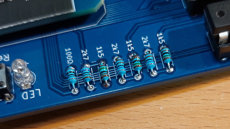
Begin with the smaller components, such as resistors and capacitors, before progressing to larger ones.
The PCB clearly labels all component values, so placement should be obvious without further explanation.
|
|
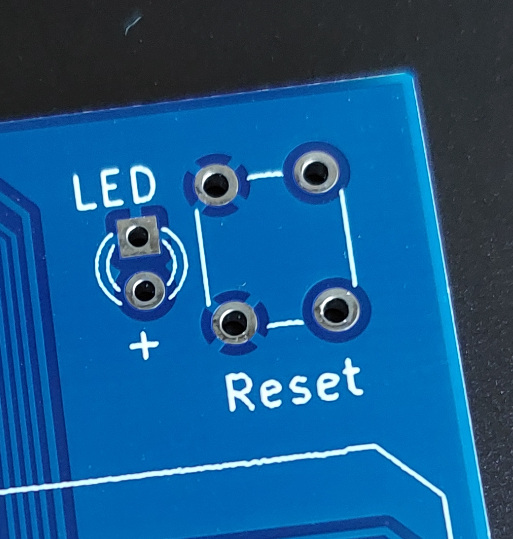
After the resistors and capacitors, proceed with the LED, reset switch and ic sockets. Do not install the ic's into the sockets just yet. Save that for last.
NOTE: take special care with placing the LED. The longer leg of the LED indicates the positive side, as marked on the pcb with a plus sign.
|
|
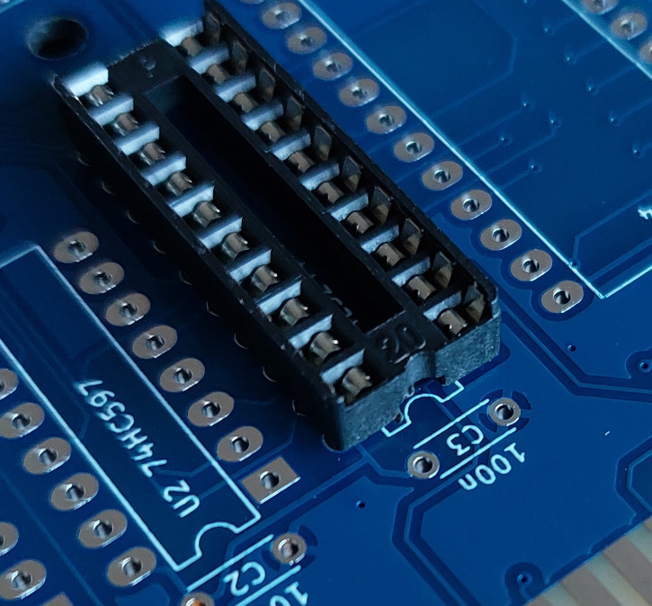
ALSO: Take notice of the orientation of the ic sockets. One side of the socket has a small indentation, that indentation should line up with the drawing on the pcb.
|
Soldering the ESP32. |
|
|
When soldering the ESP32 module on to the pcb, make sure all pins are soldered in straight.
TIP:
To make sure everything lines up, put the pin headers in first, don't solder them yet!.
Next put the ESP32 on top of the pin headers.
Now, solder one or two pins on each row on the top side of the ESP Module.
Then, solder one or two pins per row on the bottom side of the pcb.
Next, make sure everything is straight and as close to the pcb as possible, otherwise there is a risk that the cartidge enclosure does not fit.
Finally go ahead and solder all pins on both sides (the top of the ESP module and the bottom of the pcb).
|
Final inspection.
Now it's time to carefully insert the chips into their respective sockets. Again, be mindful of their orientation.
Then, conduct a thorough visual inspection of the whole pcb to ensure no solder joints have been overlooked and no pins are inadvertently shorted together. A magnifying glass is helpfull for this.
The first time you fire up your C64 with the cartridge installed you will need to register it!. Please see the User Manual for details about that!
|
